
A distributor in Dubai wins a tender for 20,000 “3.5 mm stereo audio cables with microphone” for a call-centre headset rollout. The cables arrive, the audio works, and nobody can be heard. The plugs are three-pole: two channels and a ground, no microphone contact at all. The replacement order is placed with the words “4-pole, with mic”, the samples pass, and the first bulk shipment still fails in the field — because the factory built the four-pole plug to the OMTP wiring while the headsets in the tender were wired to CTIA. Two orders, one phrase, three different products, and the phrase itself was never wrong. It was simply incomplete.
Audio cable is the least standardised family in the whole cable catalogue, and the reason is historical rather than technical. Power cords are governed by plug standards, network cable by category specifications, HDMI by a licensed specification with a compliance test. Audio grew instead out of telephony switchboards, broadcast desks, consumer hi-fi and, most recently, mobile headsets, and each of those worlds built its own connectors and its own vocabulary. The result is that a single 3.5 mm shell can be a mono instrument lead, a stereo line cable, a balanced mono interconnect, a headset cable with a microphone, or a composite video lead, and the outside of the plug tells you nothing about which one you are holding.
This guide separates the five signal families a buyer is actually purchasing, then walks through each connector family in turn: what it is defined to do, what it is commonly misused for, what to write on a purchase order, and which failures show up at goods-in rather than in the field. Where a figure comes from a standard or a manufacturer datasheet it is cited in the sources at the end; where a figure is arithmetic performed on those numbers, it is labelled as such.
Five signal families, five different cables
The single most useful question to ask before quoting an audio cable is not “what connector?” but “what signal level?” A microphone produces millivolts, an instrument pickup produces a high-impedance signal that a cable can audibly load, a line output sits at around a volt, a loudspeaker line carries volts and amperes, and a digital interface carries a shaped bitstream whose only requirement is that the receiver can recover a clock. The same copper can serve several of these, but the construction, the shielding and the connector do not interchange freely.
| Signal family | Nominal level | Usual connector | Cable construction | Practical run |
|---|---|---|---|---|
| Microphone, balanced | Millivolts | XLR 3-pin | Shielded twisted pair, 2 conductors + shield | Long; the differential input does the work |
| Instrument | High impedance, low level | 6.35 mm TS | Single conductor + shield | Short; cable capacitance is audible |
| Line, consumer | −10 dBV = 0.316 V RMS | RCA, 3.5 mm TRS | 2 conductors + shield, often twin | Under 3 m by preference |
| Line, professional | +4 dBu = 1.228 V RMS | XLR, 6.35 mm TRS | Shielded twisted pair | Long, within a building |
| Loudspeaker | Volts and amperes | Bare wire, 6.35 mm TS, speakON | 2-core, unscreened | Set by conductor gauge, not by shielding |
| Digital S/PDIF, coaxial | 0.5–0.6 V peak to peak | RCA or BNC, 75 Ω | 75 Ω coaxial | 100 m in the standard; far less in practice |
| Digital S/PDIF, optical | Light, 650 nm class | TOSLINK | PMMA optical fibre | 10 m |
| Digital AES3 | 2–7 V peak to peak | XLR 3-pin, 110 Ω | 110 Ω shielded twisted pair | Up to 1,000 m |
Table 1 — the same catalogue page, five different electrical products. Levels are nominal, not maximum: real programme material has a crest factor of 20 dB or more above nominal, which is why headroom matters more than the nominal figure. Digital distances are the values given in the published AES3/S/PDIF comparison.
Two consequences follow immediately, and both are commercial. First, a quotation that compares “audio cables” across suppliers without fixing the signal family is not comparing products; it is comparing the word. Second, the cable that is cheapest to build — two conductors, spiral shield, moulded plugs — is genuinely adequate for one of these families and genuinely wrong for the other four. That is not a quality argument. It is a specification argument, and it is settled on the drawing rather than in the negotiation.
The 3.5 mm family: TS, TRS, TRRS and TRRRS
The 3.5 mm plug is a cylindrical connector with two to five contacts, invented in the 1950s as a two-conductor earpiece plug for transistor radios and standardised in its miniature form through JEITA/EIAJ practice. The contacts are separated by insulating bands and named from the tip: tip, ring 1, ring 2, ring 3, and sleeve. The sleeve is normally the common ground or return, so the number of independent signals is always one fewer than the number of contacts. A typical plug is about 15 mm long, and the 2.5 mm and 6.35 mm versions are the same design at different diameters rather than different designs.
Because the shell is identical, the contact count and the wiring are the only things that distinguish one product from another — and neither is visible once the moulding is closed. This is the heart of the problem described at the start of this article.
TS — two contacts, mono, unbalanced
A TS plug carries one signal on the tip and the return on the sleeve. In 6.35 mm it is the electric-guitar lead; in 3.5 mm it is the mono link cable on a small speaker or an old dictaphone. It is unbalanced by construction: there is no second conductor to carry an inverted copy of the signal, so any interference voltage induced in the cable is added to the signal and delivered to the input. Its correct commercial niche is short runs at instrument or line level, and its incorrect niche is anything that will be handled roughly at a distance from the amplifier.
TRS — three contacts, and two completely different products
A TRS plug adds one ring. What that ring means depends entirely on the equipment on both ends, and this is the most expensive ambiguity in the audio catalogue. In consumer equipment the three contacts are left, right and ground: an unbalanced stereo cable. In professional equipment the same three contacts are hot, cold and shield: a balanced mono cable. The metal is identical; the electrical function is not. A stereo 3.5 mm cable used as a balanced mono lead will short the cold leg to ground at one end, which costs 6 dB of level and destroys the common-mode rejection that the balanced connection existed to provide. The reverse mistake — a balanced TRS lead used as a stereo cable — produces a mono sum or a channel loss, depending on which contact lands where.
There is a third use that surprises buyers outside the music trade: TRS is also the physical layer of MIDI, on 3.5 mm mini-jacks in the MIDI 2.0 hardware specification and on 6.35 mm in older equipment. A cable sold as “TRS” may therefore be intended for a data link with no audio content at all.
TRRS — four contacts, and two incompatible standards
A TRRS plug adds a second ring and is the standard headset connector: stereo output plus a mono microphone return, sharing a common ground. It is also used for stereo audio plus composite video on some camcorders and single-board computers, with pin assignments that are manufacturer-specific and unrelated to headsets. For a B2B buyer the headset use is the one that matters, and it splits into two wiring conventions that are electrically incompatible.
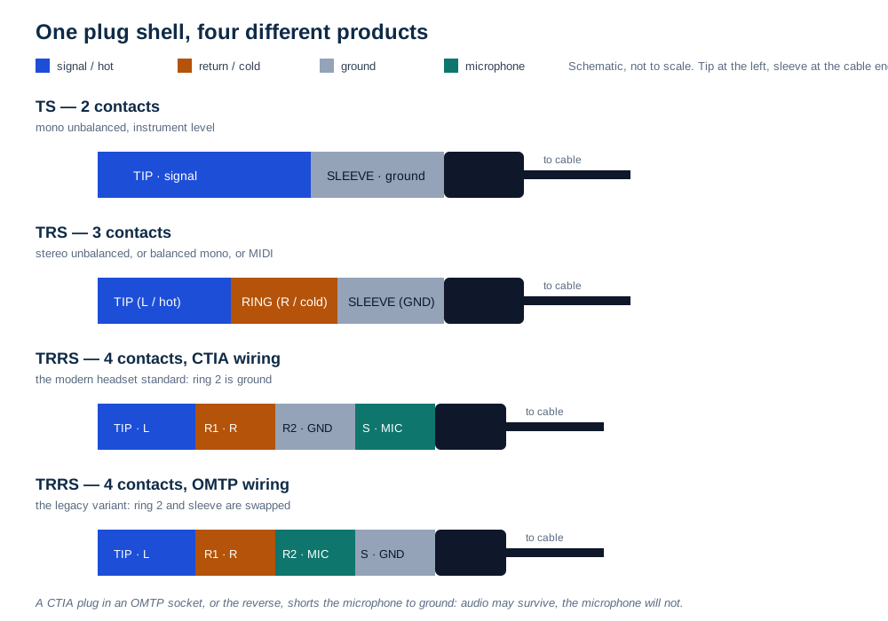
CTIA, also called AHJ, is the modern convention used by Apple, Samsung and most Android devices built after 2013, and by essentially every laptop with a single combo jack. OMTP is the legacy convention associated with Nokia, older Samsung and Sony Ericsson handsets, and with the first-generation PlayStation Vita. The difference is a single swap: CTIA puts ground on ring 2 and the microphone on the sleeve, OMTP puts the microphone on ring 2 and ground on the sleeve.
| Contact | CTIA / AHJ (modern) | OMTP (legacy) |
|---|---|---|
| Tip | Left channel | Left channel |
| Ring 1 | Right channel | Right channel |
| Ring 2 | Ground | Microphone |
| Sleeve | Microphone | Ground |
| Result of a mismatch | Audio may play but sound thin or distorted; the microphone is shorted to ground and does not work; inline remote buttons behave unpredictably | |
Table 2 — the four contacts of a headset plug. The whole difference between a working and a non-working order is which of the last two rows is which, and it cannot be seen on a finished cable.
TRRRS — five contacts, and a different job again
Five-contact plugs exist for balanced stereo headphones, where each channel needs its own pair, and for headsets with two microphones or active noise cancellation. They are a genuine product, but they are a small-volume, application-specific one: a five-contact plug is not a “better” four-contact plug, and a device that expects four contacts will not use the fifth. Buyers who see a five-pole option on a quotation should confirm which device family it is for before treating it as an upgrade.
The 6.35 mm family: one connector, three jobs
The 6.35 mm plug, the original quarter-inch telephone switchboard connector, is the same three-contact geometry at a larger diameter, and it survives in studios and on stage for three unrelated reasons. As a TS plug it is the instrument cable: a high-impedance pickup sees the cable capacitance directly, so a long lead rolls off the top end, which is why guitarists hear a difference between cables that measure identically at DC. As a TRS plug it is the balanced line connector of the professional studio, used on patch bays, insert points and monitor sends. As a TRS plug it is also the stereo headphone connector, unbalanced, with left, right and ground. The plug does not tell you which of the three you have.
The practical consequence is a cable schedule that has to be read against the equipment manual rather than against the connector. A patch bay built on 6.35 mm jacks is usually balanced, and a patch lead that has been assembled from a stereo headphone cable will “work” — signal passes — while losing the cold leg and with it the noise rejection the balanced architecture was bought for. Insert points are worse: a TRS insert cable is a Y-cable that carries send on the tip and return on the ring, so a straight TRS lead inserted into an insert point passes the send back to the return and produces either silence or a feedback path, depending on the console.
For buyers, the specification line that prevents most of this is dull and effective: state the application, the signal type and the wiring, not the plug. “6.35 mm TRS male to male, balanced, tip hot, ring cold, sleeve shield, 1.5 m, for patch bay” is a product. “6.35 mm stereo cable” is a conversation.
RCA: consumer line level, and a second life as digital coax
The RCA connector is a single-conductor coaxial plug with a centre pin and an outer shell, introduced for phonograph wiring and now the default unbalanced connector of consumer audio and video. It is used for four different jobs that share nothing but the shell: analogue line-level audio (red for right, white or black for left), composite video (yellow), component video (green, blue, red), and S/PDIF digital audio on coaxial cable, conventionally colour-coded orange. Multi-channel bundles are sold as “2RCA” or “3RCA” assemblies, and the phrase describes the count, not the function.
The audio use is straightforward and cheap: two conductors plus a shield, moulded plugs, colour-coded boots so a consumer can connect it without instructions. The digital use is where the specification matters, because S/PDIF over copper is a 75 Ω transmission line carrying 0.5–0.6 V peak to peak, and the impedance is a property of the cable geometry — conductor diameter, dielectric spacing, shield — not of the connector. A thin, high-capacitance audio lead with RCA plugs will often carry S/PDIF over one metre and fail at five, and it will fail more readily at 192 kHz than at 44.1 kHz, because the bit rate rises while the line stays the same. The symptom is not a graceful degradation: the receiver either locks or it does not, and intermittent lock sounds like a click or a dropout.
This is the one place in the audio catalogue where a video cable is the better audio cable. A 75 Ω coaxial lead, whether sold for composite video or for digital audio, has the geometry the interface expects. Our coaxial cable range covers the 75 Ω constructions used for both, and the same cable family is what a CCTV or set-top-box install consumes.

XLR: the balanced connector, and the one with rules attached
The three-pin XLR is a circular, latched, shielded connector that has been the professional audio default since the 1960s. Three contacts do three jobs: pin 1 is the shield and chassis reference, pin 2 is hot and pin 3 is cold. The latch matters more than it looks: a connector that cannot be pulled out accidentally is worth money in a venue, and the shell-to-shell bond gives the shield a low-impedance path at radio frequencies that a moulded plastic plug cannot match.
The connector is also mechanically over-specified for audio, which is useful. Published data for a standard three-pole cable connector gives 16 A per contact and a 50 V rating, figures that exist because the same shell family is used for loudspeaker and power applications. They say nothing about the cable behind the connector, and a buyer who reads 16 A as a cable rating has misread the datasheet in the expensive direction.
Two rules travel with the connector. The first is the shield: in a balanced system the shield is bonded to the chassis at both ends, at the point where the cable enters the equipment, which is the practice described in AES48 and in the Rane note cited below. The second is phantom power: condenser microphones are powered by 48 V DC applied equally to pins 2 and 3 through matched 6.81 kΩ resistors, with the return on pin 1, as defined in IEC 61938 and known as P48. The resistors must be matched to about 0.1% or the common-mode rejection of the whole input degrades, and the standard allows up to 10 mA per microphone.
Phantom power is the reason a cheap adapter can destroy an expensive microphone. A 3.5 mm plug-in-power microphone expects a few volts on the signal conductor with the return on the sleeve; a 3.5 mm to XLR adapter that ties the XLR shell to the 3.5 mm sleeve creates a path for 48 V to appear where the microphone expects 3–5 V. The adapter is sold as a convenience and used without a second thought, and the failure is attributed to the microphone.

Balanced against unbalanced: what the extra conductor actually buys
An unbalanced connection carries the signal on one conductor and uses the shield as the return. Any voltage induced in that conductor by a nearby mains cable, a dimmer or a radio transmitter is in series with the signal and arrives at the input as part of it. There is no second copy of the signal to compare against, so nothing in the receiver can tell signal from interference. That is the whole of the mechanism, and it explains why unbalanced connections are perfectly adequate in a living room and unreliable in a rack full of equipment.
A balanced connection carries the signal twice: once on the hot conductor and once, inverted, on the cold conductor, with the shield as a separate screen. Interference arrives at both conductors with the same amplitude and the same polarity, because they are twisted together and see the same electromagnetic field. The input stage subtracts one from the other, so the signal — which is inverted between the two — doubles, and the interference — which is not — cancels. The measure of how well it cancels is the common-mode rejection ratio, and it is a property of the input stage rather than of the cable. The cable's job is narrower and absolute: keep both conductors electrically identical, so that the interference really is common to both.
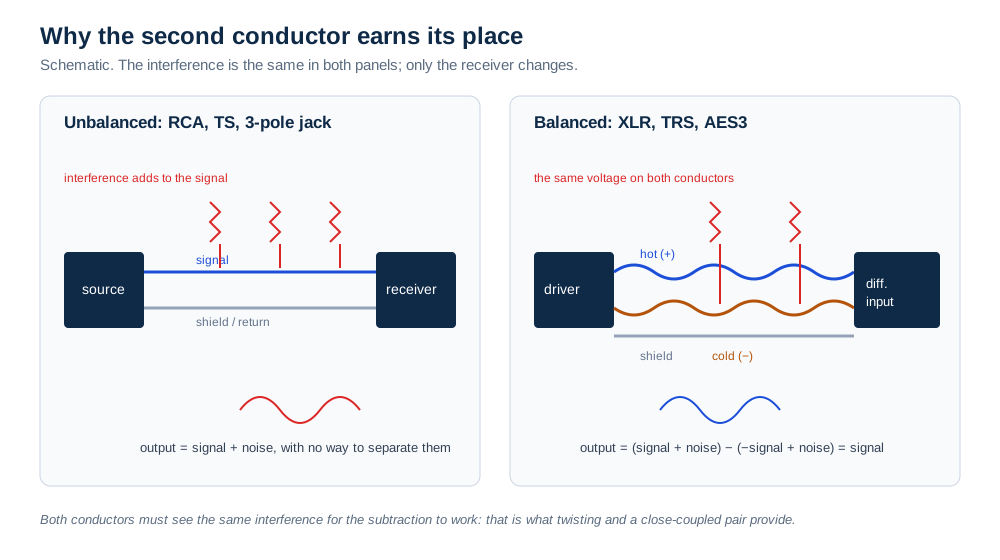
Two numbers turn this into a purchasing rule. The first is a length rule from Rane's long-standing technical note on sound system interconnection: an unbalanced cable should be kept under ten feet, about three metres, because longer runs amplify the side effects of ground loops. The second is the level penalty when a balanced output is connected to an unbalanced input: 6 dB of signal is lost, and the connection must be made with a cable that ties cold to ground at the receiving end, not by shorting the two conductors together at the plug. Both figures are engineering practice rather than regulation, and both are worth writing into an installation note rather than leaving to the installer.
Interconnection is deliberately not impedance-matched. A line output typically presents 100 to 600 Ω and a line input 10 kΩ or more, a bridging arrangement in which almost all of the voltage appears across the input and almost no current flows. Audio cables are electrically short at audio frequencies, so transmission-line thinking does not apply — which is exactly why the same 75 Ω discipline becomes mandatory the moment the signal is digital and the wavelength becomes comparable with the cable.
Grounding is the part that surprises buyers because it is invisible in a quotation. A balanced cable has its shield bonded to the chassis at both ends in the AES48 arrangement, and that is correct when both pieces of equipment are internally grounded properly. When they are not — and plenty of equipment is not — the shield carries a current between two chassis at slightly different potentials, and the result is hum at mains frequency and its harmonics. The remedies are transformer isolation, or a cable with the shield disconnected at the receiving end. Neither is a cable-manufacturing defect, and neither can be diagnosed from a datasheet.
Inside the jacket: the four numbers that decide whether the cable works
An audio cable is a small number of decisions repeated along a length: conductor material and gauge, insulation, twisting, shielding, and jacket. Each one has a measurable consequence, and only one of them is usually quoted in a quotation.
Conductor. Stranded copper, typically 20 AWG to 26 AWG for signal cable, tinned where corrosion resistance matters. Copper-clad aluminium is not a substitute: at the same gauge it carries roughly 1.6 times the resistance of copper, and in a signal cable that also means more susceptibility to picking up noise. The gauge arithmetic, the class definitions and the CCA problem are covered in our AWG and mm² guide, and the same rules apply here at smaller sizes.
Twisting. A balanced pair must be twisted, with a short lay length, so that both conductors see the same field along the whole run. A pair that is merely two parallel wires inside a shield is balanced on paper and unbalanced in a strong field.
Shielding. Foil gives 100% coverage and no flexibility; braid gives mechanical strength and a defined coverage percentage; foil plus braid gives both at a cost; a spiral serve is cheap and opens gaps when the cable is flexed. The construction, the coverage figures and the termination rules are set out in our cable shielding guide, and the audio-specific point is that the shield is a screen, not a conductor: it must be terminated, not used to carry signal return in a balanced system.
Capacitance. This is the number that predicts high-frequency loss, and it is the one buyers almost never ask for. A published digital microphone cable in the Belden 1800F family is specified at 110 Ω with 39 pF/m. Put 100 m of that cable in front of a 10 kΩ line input and the capacitance is 3.9 nF; the resulting single-pole roll-off, f = 1/(2πRC), lands at about 4.1 kHz. At 30 m the same arithmetic gives about 13.6 kHz. Neither figure is a defect — the cable is doing exactly what its capacitance says it will do — but both explain why a run that was specified as “100 m of mic cable” can arrive as a muffled channel and be blamed on the microphone.
| Parameter | What it controls | Typical range for signal cable | What happens if it is left out of the order |
|---|---|---|---|
| Conductor gauge and material | Resistance, mechanical strength, cost | 20–26 AWG stranded bare or tinned copper | A lighter, stiffer cable at the same outside diameter |
| Pair twisting | Whether interference is genuinely common-mode | Twisted pair, short lay length | A balanced cable that hums in a strong field |
| Shield type and coverage | Radio-frequency and electrostatic pickup | Foil plus braid, or braid alone | Buzz near dimmers and radios; no defined coverage figure |
| Capacitance per metre | High-frequency roll-off with the input impedance | Around 39 pF/m for a 110 Ω digital pair | A long run that sounds dull and measures “fine” for continuity |
| Jacket material | Flex life, flame behaviour, feel | PVC, PU, LSZH compound | A cable that hardens in a cold room or fails a fire requirement |
| Length tolerance | Whether the delivered length is the ordered length | Stated plug-face to plug-face, with a tolerance | Disputes at goods-in that cannot be resolved from the invoice |
Table 3 — six lines that turn “good quality audio cable” into something a factory can build and a laboratory can check. The capacitance figures in this table are taken from published cable data and the roll-off figures in the text are arithmetic performed on them, not measurements of a specific shipment.
Loudspeaker cable is not a signal cable
A loudspeaker cable carries power, not information at a low level, and its specification is therefore about resistance and current rather than shielding and capacitance. Two unscreened cores, a gauge chosen for the current and the length, and a jacket that survives being walked on: that is the product. Screening adds capacitance and cost and removes nothing that matters, because the signal-to-noise ratio at the loudspeaker is enormous compared with a microphone line.
The common error runs in the wrong direction. A contractor short of two-core cable reaches for a reel of shielded microphone cable, and the amplifier is now driving a capacitive load through a thin conductor. An amplifier that sees a large capacitive load can become unstable, and the audible result is a hiss, a whistle or a protection shutdown rather than a clean failure, which makes it hard to diagnose. The correct product is cheaper, and the reason it exists is exactly this.
Two further points belong on a commercial order. In distributed systems — a shop, a school, an airport — loudspeakers are often fed from a constant-voltage 100 V line, where each speaker carries a step-down transformer and the cable current is small for the power delivered, so long runs become practical. And in either architecture the conductor material is not a detail: copper-clad aluminium at the same nominal area has higher resistance, which reduces damping and turns part of the amplifier's output into heat in the wall.
Digital audio interconnects: three physical layers, one bitstream
Digital audio at consumer and professional level is carried over three physical layers, and each has a different reason to exist. S/PDIF on coaxial cable is a 75 Ω unbalanced line with RCA or BNC connectors, carrying 0.5–0.6 V peak to peak, standardised as IEC 60958 type II. S/PDIF on optical fibre uses TOSLINK connectors and a PMMA fibre, with the same data and complete electrical isolation between the two devices. AES3 is the professional version, balanced on 110 Ω shielded twisted pair with XLR connectors and 2–7 V peak to peak, and it is the layer that reaches across a building.
The published comparison between the three gives maximum distances of 1,000 m for AES3, 100 m for coaxial S/PDIF and 10 m for TOSLINK. Those are standard figures under favourable conditions, and installers treat them as ceilings rather than targets: a 75 Ω lead that is actually 75 Ω, with proper connectors, will run far beyond the length at which a thin audio lead gives up, and an optical cable that has been bent through a tight radius will fail at three metres.
Optical has one property the electrical versions cannot offer: no galvanic connection at all, so a ground loop between a television and an amplifier simply cannot form through the cable. That is worth paying for in a mixed installation, and it is the reason TOSLINK survives despite its fragility and its 10 m limit. The failure mode is also distinctive: if the red light is visible at the far end and there is still no audio, the problem is at one of the devices rather than in the fibre.

The naming trap: seven phrases that sound like a specification
Every phrase in the table below appears on real purchase orders, and none of them is false. Each one can be read in at least two ways by two competent factories, and the difference between the readings is a different product. The pattern is consistent: the phrase describes the shape of the connector, and the product is defined by the wiring and the electrical role.
| What the buyer writes | What it can legitimately mean | What breaks if it is read the other way |
|---|---|---|
| “3.5 mm stereo cable” | 3-pole TRS, or 4-pole TRRS with a microphone contact | A headset order that arrives without a microphone circuit — the failure at the top of this article |
| “TRS cable” | Unbalanced stereo, or balanced mono, or a MIDI lead | A balanced run that loses 6 dB and all of its noise rejection |
| “AUX cable” | Any cable with a 3.5 mm plug, including a 4-pole headset lead | A microphone shorted to ground, or one channel missing, on a device that expects 3-pole |
| “75 Ω RCA cable” | 75 Ω coaxial with RCA plugs, or an audio lead with RCA plugs and a 75 Ω label | A S/PDIF link that locks at 44.1 kHz and drops out at 192 kHz |
| “Microphone cable” | Balanced XLR, or 3.5 mm plug-in-power for a consumer microphone | 48 V phantom power presented to a microphone rated for 3–5 V |
| “Audio extension cable” | 3-pole male-to-female, or 4-pole headset extension | A working pair of headphones and a dead microphone, on an accessory sold as compatible |
| “OFC / pure copper” | Any copper conductor, of any purity, strand count or anneal | Higher resistance than the sample, and no measurement to hold anyone to |
Table 4 — seven phrases, each with a documentary answer: connector, contact count, wiring convention, signal type, cable construction and a measurable electrical limit.

Five errors, and what each one costs
1. Specifying the contact count without the wiring standard. “4-pole TRRS” is satisfied by two incompatible products. Cost: a full production run that cannot be reworked, because the plug is moulded onto the cable, and a field failure rate that looks like a quality problem and is actually a specification problem.
2. Selling a 3-pole extension as a headset accessory. The customer hears audio and cannot be heard, concludes the headset is faulty, and returns both. Cost: a support case per unit, a marketplace rating that follows the listing, and a reshipment that repeats the fault because the catalogue was never corrected.
3. Combining two outputs with a Y-splitter. A passive splitter used in reverse ties two low-impedance outputs together, and each tries to drive the other as well as the load. Cost: distortion at best, damage to an output stage at worst — and the splitter is the cheapest item in the bill of materials.
4. Running unbalanced audio across a room. A ten-metre RCA lead from a laptop to an amplifier picks up mains hum and rolls off the top end, and the customer blames the amplifier. Cost: a technical support call that cannot be resolved by replacing the unit, because the unit is not at fault.
5. Bonding the shield at both ends of an unbalanced cable. The shield becomes a conductor between two chassis at different potentials, and the hum is now built into the cable. Cost: a cable that measures perfectly and hums in every installation.
What to put on the purchase order
The list below replaces every phrase in Table 4. It is written for a cable assembly, not for a reel, because that is where the ambiguity costs the most: a reel of the wrong cable can be cut down, a moulded assembly cannot.
| # | Field | Usable value | Why it earns its line |
|---|---|---|---|
| 1 | Signal family | Microphone, instrument, line, loudspeaker or digital | Decides everything below it |
| 2 | Connector, both ends | 3.5 mm TRS male to 3.5 mm TRS male, or XLR 3-pin male to female | Removes the “stereo cable” ambiguity |
| 3 | Contact count | 2, 3, 4 or 5, stated as a number | A moulded plug cannot be changed after assembly |
| 4 | Wiring convention | CTIA for TRRS; tip hot, ring cold, sleeve shield for balanced TRS | The one line that separates two incompatible products |
| 5 | Cable construction | 2 conductors + shield, twisted pair, 24 AWG stranded copper | Sets resistance, capacitance and flex life |
| 6 | Shield and termination | Braid coverage %, foil, drain wire; bonded both ends or one end | Decides whether the cable hums before it is used |
| 7 | Maximum resistance or capacitance | Ω/km per conductor, or pF/m, at 20 °C | The number a test house can hold a supplier to |
| 8 | Length and tolerance | 1.5 m plug face to plug face, ±20 mm | Ends the length argument at goods-in |
| 9 | Jacket and colour | PVC or LSZH, colour, print or no print | Compliance and shelf identity |
| 10 | Test evidence | 100% continuity and pinout test, sample capacitance and insertion force | Converts a claim into a batch record |
Table 5 — ten lines that replace “3.5 mm stereo cable, good quality”. Fields 3, 4, 5 and 7 do the work; the rest prevent a substitution inside the same shipment.
The same discipline applies across the range. A 3.5 mm or RCA assembly order needs the contact count and the wiring convention; an audio switch or splitter order needs to state whether the splitter is passive or active, because a passive Y-cable cannot combine two outputs; and a 75 Ω coaxial order needs the impedance and the connector, since the same RCA shell is used for two different electrical products.
Three checks anyone can run at goods-in
The first is a pinout test, and it needs nothing more than a multimeter with a continuity buzzer. For a TRRS cable, confirm tip to tip, ring 1 to ring 1, ring 2 to ring 2 and sleeve to sleeve, then confirm that no contact is shorted to its neighbour. A CTIA cable cannot be distinguished from an OMTP cable by continuity alone, because both are straight-through; the difference is in the device, so the sample must be plugged into a known CTIA device and its microphone tested. That single test is worth more than any certificate for this product family.
The second is capacitance, measured on a sample with an LCR meter across the two conductors, then compared with the figure on the drawing. A cable that measures twice its specified capacitance will roll off at half the frequency, and the effect is inaudible on a bench test with a phone and obvious on a 50 m install.
The third is mechanical: insertion and withdrawal force on the plug, a bend cycle at the strain relief, and a pull test on the moulding. Headset cables fail at the plug far more often than in the middle, and a moulded strain relief that is too stiff transfers the bend into the conductor bundle two centimetres behind it. None of these three checks requires a laboratory, and together they predict field behaviour better than the datasheet does.
FAQ
Is a TRRS cable just a TRS cable with a microphone? Electrically, yes: it adds a fourth contact for a microphone return. Commercially, no, because the fourth contact has two incompatible assignments. A TRRS cable built to CTIA will not work as a headset cable on an OMTP device and vice versa, and a three-pole TRS cable will never carry a microphone at all. If the product is a headset accessory, the wiring convention belongs on the drawing next to the contact count.
Can I use a 3.5 mm to XLR adapter with phantom power? Not safely with a plug-in-power microphone. The adapter can connect the XLR shell to the 3.5 mm sleeve, and 48 V then appears where the microphone expects 3–5 V. If phantom power cannot be switched off at the input, use a transformer-isolated adapter or a dedicated interface rather than a passive cable. A dynamic microphone with a balanced output is a different case, but the adapter itself is still the weak point, because it cannot maintain the balanced wiring.
How long can an unbalanced RCA run be? Three metres is the working limit quoted in professional practice, and it is a limit on hum and interference rather than on signal loss. Beyond that, the practical answer is to convert to balanced at both ends with a transformer or a direct box, or to go digital over 75 Ω coaxial or optical fibre. A ten-metre RCA lead will usually produce sound; the question is what else it produces.
Does gold plating matter? It matters for corrosion and contact resistance in humid or frequently re-mated connections, and it does nothing for sound quality in a dry, static installation. What matters more is the plating under the gold: gold over nickel is durable, gold directly over brass is not, and a very thin flash is cosmetic. For a marine or tropical destination market, gold over nickel is a reasonable specification; for a fixed installation, nickel is adequate and cheaper.
What is the difference between 2RCA and 3RCA? Only the number of connectors in the assembly. 2RCA carries stereo audio, left and right. 3RCA carries either composite video plus stereo audio, or three-wire component video, depending on the colour code and the equipment. The phrase describes the count, so it cannot be used to infer the function, and a 3RCA order should always state which signal goes to which colour.
Can I use a shielded cable for loudspeakers? You can, and it will usually work, but you are paying for a screen you do not need and adding capacitance the amplifier has to drive. In a long run with a high-capacitance cable, some amplifiers become unstable. Two unscreened cores of adequate gauge are cheaper, more flexible and electrically better for the job.
Conclusion
Audio cable is not one product with several plugs; it is five electrical families that happen to share a catalogue page. The signal level decides the cable construction, the construction decides the shield and the capacitance, and the connector decides only the mechanics. Once those three are fixed, the remaining variable — the wiring convention inside a four-contact plug — is the one that produces the failures nobody can see, because it is decided by a moulding tool and discovered by a customer.
Guangzhou Senye Network Technology Co., Ltd. has been building cable assemblies since 2011, with more than 1,000 models across HDMI, USB, power, network, audio, video and coaxial lines, exported to more than 40 countries. Our audio range covers 3.5 mm TS, TRS and TRRS assemblies, 6.35 mm instrument and patch leads, 2RCA and 3RCA leads, XLR microphone cables and TOSLINK optical cables, in PVC or LSZH jackets and in custom lengths and colours. Production is CE and RoHS compliant, the factory is SGS-audited, and every assembly is ageing tested before packing; OEM and ODM orders are welcome, with the wiring convention, contact count and test criteria written into the drawing before the first sample is built. If you are sourcing an audio cable and the quotation only names a connector, send us the application and we will write the specification with you.
Sources
Wikipedia, Phone connector (audio) (retrieved 2026-11): the 2-to-5 contact family, tip/ring/sleeve naming, the 6.35 mm, 3.5 mm and 2.5 mm diameters, the 15 mm miniature plug length, the TS/TRS/TRRS/TRRRS use table and the note that a TRS plug serves stereo, balanced mono and MIDI. Hardwarebook, 3.5mm TRRS (last modified 2026-08-11): the CTIA and OMTP contact assignments used in Table 2, the compatibility outcomes of a mismatch, and the 4-pole plug reference data. Rane Corporation, RaneNote 110: Sound System Interconnection (written 1985, revised 11/15): the requirement for twisted-pair balanced interconnect, shield bonding to chassis at both ends per AES48, transformer isolation for unbalanced equipment, the 6 dB loss when a balanced output feeds an unbalanced input, and the rule that unbalanced cable should be kept under ten feet (three metres). Rane Corporation, RaneNote 109: Why Not Wye? (April 2004), for the prohibition on tying two outputs together with a Y-cable. Wikipedia, Line level (retrieved 2026-11), citing RaneNote 126: the +4 dBu and −10 dBV nominal levels and their voltages, the 100–600 Ω output and 10 kΩ input impedances, and the bridging principle. Wikipedia, Phantom power (retrieved 2026-11): IEC 61938 P48 operation, the 6.81 kΩ matched feed resistors, the 0.1% matching requirement, the 10 mA per-microphone limit, and the warning about 3.5 mm to XLR adapters. Wikipedia, S/PDIF (retrieved 2026-11): IEC 60958 type II, the AES3/S/PDIF comparison of 110 Ω balanced against 75 Ω coaxial and optical, the 2–7 V, 0.5–0.6 V output levels, and the 1,000 m, 100 m and 10 m maximum distances. Belden, 1800F digital microphone cable datasheet: 110 Ω nominal impedance and 39 pF/m capacitance. Neutrik NC3FXX three-pole cable connector published data, as listed by distributors: 16 A current rating per contact and 50 V rating. Note: the capacitance roll-off figures in this article (about 4.1 kHz at 100 m and 13.6 kHz at 30 m into 10 kΩ) are arithmetic derived from the cited capacitance and impedance values using f = 1/(2πRC). They are indicative and should be replaced by a test report for any contractual purpose.